Key Takeaways
- Core idea: Foundation design transfers structural loads into soil or rock while controlling bearing failure, settlement, lateral movement, uplift, and construction risk.
- Engineering use: Engineers use foundation design to choose between footings, mats, piles, drilled shafts, ground improvement, or hybrid support systems.
- What controls it: Settlement, groundwater, eccentric loading, weak layers, uplift, and constructability often control the foundation type more than the first bearing-pressure check.
- Practical check: A safe foundation is not proven by one bearing equation; it must also satisfy movement, stability, detailing, and field-verification requirements.
Table of Contents
Introduction
Foundation design is the process of selecting and sizing a foundation system so building, bridge, tower, tank, wall, or equipment loads are safely transferred into soil or rock. A good design controls bearing pressure, settlement, differential movement, sliding, overturning, uplift, groundwater effects, and construction practicality rather than relying on a single calculation.
Foundation Design Workflow
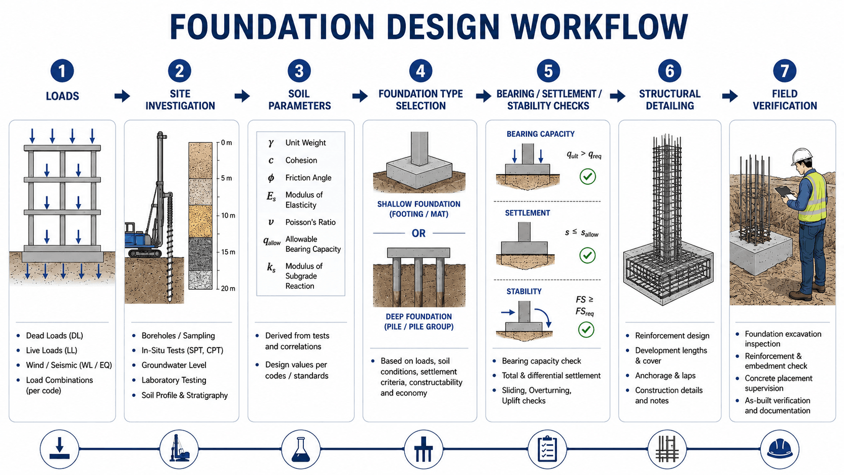
The workflow is: define loads, investigate the site, interpret soil parameters, select a foundation type, check bearing/settlement/stability, coordinate structural detailing, and verify field conditions before and during construction.
What is Foundation Design?
Foundation design is the engineering process that connects a structure to the ground. The design must determine how loads move from columns, walls, slabs, frames, or equipment into a foundation element and then into soil or rock without exceeding strength, movement, or stability limits.
In geotechnical engineering, foundation design is not only about making a concrete footing large enough. It is about matching the structure to the subsurface profile. A light building on dense sand may use shallow spread footings, while a heavy structure on soft clay may need a mat, pile foundations, drilled shafts, or ground improvement before the same loads can be supported reliably.
The goal is not simply to prevent collapse. A successful foundation must also limit settlement, differential movement, cracking, rotation, water-related problems, long-term deterioration, and construction surprises.
What a Geotechnical Report Provides for Foundation Design
The geotechnical report is the bridge between subsurface exploration and foundation design. It converts borings, in-situ tests, groundwater observations, laboratory data, and site history into design recommendations that the structural design can use.
| Geotechnical report item | How it supports foundation design | Design question it helps answer |
|---|---|---|
| Recommended foundation type | Identifies whether shallow foundations, mats, piles, drilled shafts, or ground improvement are likely suitable. | What foundation systems should be considered first? |
| Allowable bearing pressure or nominal resistance | Provides soil or rock resistance values for footing sizing, mat evaluation, or deep foundation capacity checks. | How much load can the ground support under the selected design approach? |
| Settlement estimates | Evaluates total settlement, differential settlement, and time-dependent consolidation where relevant. | Will the foundation move too much for the structure to perform properly? |
| Groundwater observations | Identifies water table, perched water, seepage, buoyancy, dewatering, and excavation stability concerns. | Will water affect bearing, uplift, construction, or long-term performance? |
| Subgrade preparation requirements | Defines proof-rolling, unsuitable soil removal, compaction, replacement fill, stabilization, or bearing surface acceptance. | What must be verified before concrete or reinforcement is placed? |
| Deep foundation recommendations | May include pile type, estimated capacity, installation criteria, testing requirements, and group-effect considerations. | How should loads be transferred when near-surface soils are not adequate? |
| Construction observation and testing | Defines the field checks needed to confirm that actual conditions match design assumptions. | How will the foundation design be verified in the field? |
Main Inputs Used in Foundation Design
A foundation design is only as reliable as the inputs behind it. The structural engineer provides loads and geometry, while the geotechnical investigation defines soil behavior, groundwater, bearing resistance, compressibility, lateral parameters, and construction risks.
| Design input | Why it matters | Engineering implication |
|---|---|---|
| Column, wall, mat, and equipment loads | Loads determine contact pressure, pile demand, overturning, uplift, and reinforcement requirements. | Higher loads may push the design from isolated footings to combined footings, mats, piles, or drilled shafts. |
| Soil stratigraphy and boring depth | Layer thickness, weak seams, fill, rock depth, and variability affect how load spreads and where failure or settlement may occur. | A shallow footing may be acceptable on dense near-surface soil but unreliable above soft clay, loose fill, or highly variable deposits. |
| Groundwater table | Water changes effective stress, excavation behavior, uplift, buoyancy, corrosion exposure, and construction sequencing. | High groundwater can make a shallow design more difficult even when bearing capacity appears adequate on paper. |
| Settlement tolerance | Serviceability often controls foundations before ultimate bearing failure is reached. | Equipment pads, masonry walls, tanks, and brittle finishes may require tighter differential settlement limits. |
| Lateral, seismic, wind, and uplift demands | Foundations must resist more than vertical gravity load. | Retaining walls, towers, canopies, seismic load combinations, and overturning moments can control foundation dimensions or pile layout. |
| Construction access and sequencing | The best theoretical system may be impractical if it cannot be excavated, dewatered, reinforced, inspected, or built safely. | Constructability can change the preferred design from a deep excavation to a mat, from a mat to piles, or from piles to ground treatment. |
How the Foundation Design Process Works
The process starts by defining what the foundation must support and how much movement the structure can tolerate. Engineers then use the geotechnical report to build a ground model, screen foundation types, check performance, coordinate structural detailing, and verify that field conditions match the assumptions.
1. Establish the structural demand
Loads are organized by source: dead load, live load, equipment load, wall load, wind, seismic, surcharge, lateral earth pressure, and uplift. The designer also checks whether service-level or strength-level loads are being used because settlement checks and stability checks may use different combinations.
2. Interpret the ground model
The geotechnical report should be read as a model of subsurface behavior, not just a list of allowable bearing values. Soil layers, groundwater, test results, fill history, rock depth, and variability all influence the final recommendation.
3. Screen shallow, mat, deep, and improved-ground options
Most projects begin by asking whether a shallow foundation can meet bearing and settlement criteria. If not, the design may shift toward mat foundations, raft foundations, piles, drilled shafts, or ground improvement.
4. Check performance and coordinate detailing
Geotechnical checks and structural checks must agree. The foundation may satisfy soil bearing but still require thicker concrete, additional reinforcement, shear checks, embedment, development length, or modified dimensions to support the structural load path.
Types of Foundations Used in Foundation Design
Foundation type selection should follow the controlling design problem. A footing, mat, pile, drilled shaft, or improved-ground solution is only “best” when it satisfies the actual load, soil, movement, water, and constructability requirements.
| Foundation type | Typical use | Main design concern |
|---|---|---|
| Pad foundation or spread footing | Individual columns with moderate loads on suitable near-surface soil. | Bearing pressure, settlement, eccentricity, punching shear, and reinforcement. |
| Strip foundation | Continuous walls, masonry walls, or line loads. | Uniform support, frost depth, differential settlement, wall alignment, and subgrade preparation. |
| Combined footing | Closely spaced columns or property-line columns where isolated footings would overlap or become eccentric. | Resultant location, pressure distribution, flexure, shear, and constructability. |
| Mat or raft foundation | Heavy or closely spaced loads, variable support, or cases where isolated footings become inefficient. | Total settlement, differential settlement, mat stiffness, punching shear, and soil-structure interaction. |
| Pile foundation | Weak near-surface soil, high uplift, scour, deep competent layers, or strict movement limits. | Axial capacity, group effects, installation method, lateral resistance, and testing requirements. |
| Drilled shaft | Heavy column loads, bridge piers, towers, or deep competent strata where large-diameter support is useful. | End bearing, side resistance, slurry or casing control, base cleanliness, and concrete placement quality. |
| Slab-on-grade | Floors, light structures, warehouses, pavements, and equipment areas supported by prepared subgrade. | Subgrade support, shrink-swell behavior, moisture control, jointing, reinforcement, and flatness tolerance. |
Shallow vs Deep Foundation Design
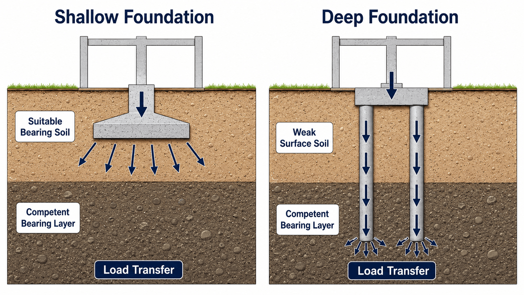
The shallow-versus-deep decision is one of the most important choices in foundation design. Shallow systems rely on near-surface soil, while deep systems bypass weak or compressible upper layers and transfer load to deeper competent soil or rock.
Check whether shallow foundations can meet bearing requirements, then settlement limits, then groundwater, frost, scour, expansive soil, and constructability constraints. If shallow foundations cannot satisfy those checks, evaluate whether ground improvement can solve the issue before moving to piles, drilled shafts, or other deep systems.
| Foundation choice | Best fit | What usually controls the decision |
|---|---|---|
| Spread footings and pad foundations | Individual columns on competent near-surface soil with manageable loads. | Bearing pressure, eccentricity, local settlement, punching shear, and reinforcement detailing. |
| Strip foundations | Continuous walls or closely spaced line loads where soil support is reasonably uniform. | Wall load distribution, differential settlement, frost depth, groundwater, and construction tolerance. |
| Mat or raft foundations | Column loads are heavy or closely spaced, or isolated footings would overlap. | Total settlement, differential settlement, mat stiffness, soil-structure interaction, and concrete detailing. |
| Pile foundations | Soft surface soil, deep competent bearing layer, high uplift, scour risk, or strict movement limits. | Shaft resistance, end bearing, group effects, lateral response, installation method, and testing plan. |
| Ground improvement plus shallow foundation | Large-footprint projects where improving the soil is more efficient than using deep foundations everywhere. | Treatment depth, method compatibility, post-treatment verification, settlement reduction, and QA acceptance criteria. |
Core Foundation Design Checks
A foundation can fail or perform poorly in several ways. The design must check strength, movement, and stability together because improving one check can sometimes worsen another. For example, making a footing larger may reduce bearing pressure but increase excavation complexity and groundwater exposure.
Bearing pressure
Bearing pressure compares the load applied to the soil against the soil resistance available below the foundation. For a simple centrally loaded footing, the average contact pressure is often introduced as:
- \(q\) Average bearing pressure, commonly expressed in psf, ksf, kPa, or MPa depending on the project.
- \(P\) Vertical load applied to the foundation, including appropriate service or strength load combinations.
- \(A\) Effective foundation contact area. Eccentric loading can reduce the effective area and increase edge pressure.
Settlement and differential settlement
Settlement is the downward movement of the foundation caused by soil deformation. Uniform settlement may be acceptable for some structures, while differential settlement can crack walls, distort frames, damage utilities, and cause serviceability problems even when bearing capacity is adequate.
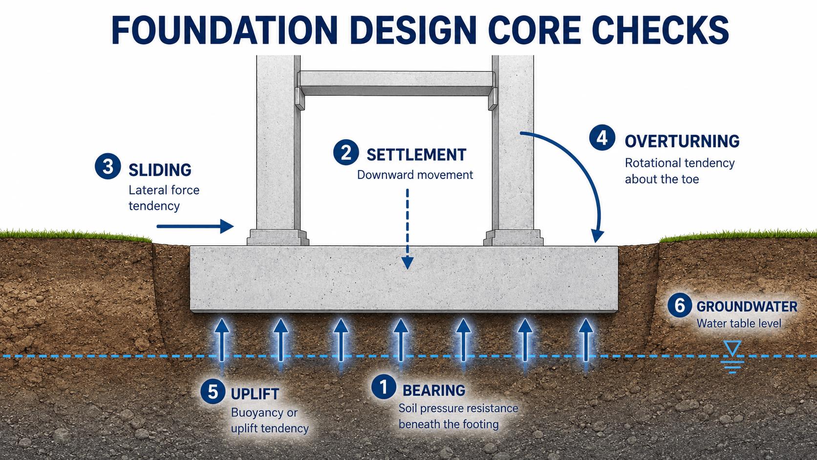
Sliding, overturning, and uplift
Lateral loads, moments, water pressure, buoyancy, and uplift can control foundations for retaining structures, towers, canopies, tanks, utility structures, and seismic or wind-sensitive systems. These checks often govern foundation footprint, embedment, weight, keying, pile layout, or anchorage.
Bearing Capacity vs Settlement: What Usually Controls?
Bearing capacity and settlement answer different design questions. Bearing capacity asks whether the soil can resist shear failure below the foundation. Settlement asks whether the foundation will move too much for the structure to remain serviceable.
| Design check | What it protects against | Why it can control the foundation |
|---|---|---|
| Bearing capacity | Shear failure, punching into weak soil, or excessive pressure below the footing. | Controls when loads are high, footings are small, soils are weak, or eccentricity causes high edge pressure. |
| Total settlement | Uniform downward movement that can affect elevations, utilities, slabs, and serviceability. | Controls where compressible layers exist below the foundation stress influence zone. |
| Differential settlement | Uneven movement between columns, walls, footings, or different parts of the same structure. | Often controls because frames, masonry, cladding, utilities, and equipment tolerate uneven movement poorly. |
| Time-dependent settlement | Continued movement after construction, especially in clay or organic soils. | Controls when settlement occurs slowly and can affect long-term performance after the structure is occupied. |
For many shallow foundations, settlement or differential settlement controls the design before true bearing failure is reached. That is why a footing can have an acceptable bearing pressure and still be too small for serviceability.
Design Approaches Used in Foundation Design
Foundation design normally separates strength, serviceability, and stability checks. A single allowable bearing value may be useful for preliminary sizing, but real design must also consider settlement performance, load combinations, resistance factors, and structural concrete behavior.
| Design approach | How it is used | What to watch for |
|---|---|---|
| Allowable bearing pressure | Often used for preliminary shallow footing sizing and service-level checks. | It may combine strength and settlement judgment, so the basis of the value should be understood. |
| LRFD or resistance-factor design | Common in transportation and infrastructure work where loads and resistances are factored separately. | The designer must use the correct load factors, resistance factors, and limit states for the foundation type. |
| Settlement analysis | Used to estimate total and differential movement under service loads. | The result depends heavily on soil compressibility, stress history, drainage conditions, and layer thickness. |
| Structural foundation design | Checks concrete thickness, reinforcement, flexure, shear, punching shear, anchorage, and detailing. | The structural element must safely transfer load into the soil resistance assumed by the geotechnical design. |
What Usually Controls Foundation Design?
Many beginner explanations make foundation design sound like a bearing capacity problem. In practice, the controlling condition may be settlement, groundwater, construction access, differential stiffness, lateral load, frost depth, scour, or the need to verify the design during construction.
| Controlling condition | What it looks like in design | Typical response |
|---|---|---|
| Soft clay or compressible organic soil | Bearing may appear acceptable at low pressure, but consolidation settlement becomes excessive. | Use a mat, preload, wick drains, lightweight fill, piles, or ground improvement depending on schedule and tolerance. |
| Loose sand or variable fill | Localized settlement and inconsistent support can control more than average pressure. | Overexcavate and replace, densify, improve the ground, or bypass the layer with deep foundations. |
| Expansive clay | Moisture changes cause shrink-swell movement that can heave slabs and shallow footings. | Use moisture control, deeper bearing, void forms, stiffened slabs, drilled piers, or soil treatment where appropriate. |
| High groundwater | Rising water reduces effective stress, can reduce soil strength, increases uplift risk, and complicates excavation. | Check buoyancy, dewatering, subgrade protection, drainage, uplift resistance, and constructability. |
| Large moments or eccentricity | Vertical load plus moment shifts the resultant, increases edge pressure, and may reduce effective bearing area. | Increase footing size, use a combined footing, tie foundations together, add piles, or revise the structural load path. |
| Frost, scour, or erosion | Minimum embedment or foundation depth may be controlled by environmental exposure rather than gravity load alone. | Place foundations below frost depth, protect against scour, deepen supports, or use deep foundations where surface soils may be removed. |
| Tight movement tolerance | Equipment alignment, masonry, glass, tanks, and utilities may not tolerate ordinary settlement. | Use stiffer foundation systems, settlement-compatible detailing, deep foundations, or improved ground. |
Geotechnical vs Structural Responsibilities
Foundation design is a coordinated geotechnical and structural task. The geotechnical side defines what the ground can support and how it may move. The structural side designs the concrete, steel, reinforcement, and load-transfer details that deliver the structural loads into that ground resistance.
| Responsibility area | Typical geotechnical role | Typical structural role |
|---|---|---|
| Foundation type selection | Identify soil conditions, bearing layers, groundwater, settlement risk, and feasible foundation systems. | Coordinate loads, column layout, foundation geometry, constructability, and structural system constraints. |
| Design parameters | Recommend bearing resistance, settlement estimates, lateral parameters, subgrade reaction, and deep foundation capacities. | Apply loads and combinations to size elements and design reinforcement, thickness, shear, and anchorage. |
| Construction verification | Observe subgrade, review unsuitable soils, confirm bearing conditions, and evaluate changed conditions. | Review reinforcement, concrete placement details, anchor locations, and structural drawing compliance. |
Senior Engineer Foundation Design Review Checklist
A strong foundation review checks whether the design answers the real project question: will this support system perform acceptably in the actual ground, during the actual construction sequence, under the actual load combinations?
Start with the load path, confirm the ground model, screen the foundation type, check bearing and settlement, verify lateral and uplift resistance, coordinate structural detailing, and define how field conditions will be accepted or corrected during construction.
| Review check | What to look for | Why it matters |
|---|---|---|
| Load basis | Service loads, strength loads, lateral loads, uplift, moments, and load combinations are clearly identified. | Using the wrong load level can make settlement checks too conservative or strength checks unconservative. |
| Ground model | Borings, test data, groundwater, fill history, weak seams, and variability are reflected in the recommendation. | Foundation failures often trace back to an incomplete or oversimplified model of the subsurface profile. |
| Bearing and settlement coordination | The design checks both allowable pressure and total or differential movement. | A foundation may be safe against shear failure but still perform poorly because of excessive settlement. |
| Eccentricity and overturning | Moments, lateral loads, edge pressure, resultant location, and stability are checked together. | Average bearing pressure can hide high edge pressure when the load is not centered. |
| Groundwater and construction stage | Dewatering, subgrade disturbance, uplift, excavation stability, and wet-weather construction are addressed. | The foundation is built before it performs; construction conditions can damage the subgrade before the structure is loaded. |
| Structural detailing | Concrete thickness, punching shear, reinforcement, cover, development length, dowels, anchors, and construction joints are coordinated. | The soil recommendation and the concrete design must work as one load-transfer system. |
| Field verification | Subgrade inspection, proof-rolling, pile testing, concrete placement observation, or as-built documentation is defined. | Verification turns design assumptions into field confidence and helps catch unsuitable conditions before they are buried. |
Worked Example: Preliminary Footing Size
A simple footing-size calculation is useful for early design, but it is only a starting point. The result must still be checked for settlement, eccentricity, shear, reinforcement, frost or embedment depth, groundwater, and field verification.
Example assumptions
- Service column load: \(P = 180 \text{ kips}\)
- Allowable bearing pressure from the geotechnical report: \(q_{allow} = 3 \text{ ksf}\)
- Preliminary centrally loaded square footing
Engineering interpretation
A preliminary square footing would be about 7.75 ft by 7.75 ft before rounding and structural detailing. In practice, the engineer might round up, check settlement and differential settlement, verify pressure distribution under eccentric loading, design the concrete reinforcement, and confirm the bearing surface during excavation.
This example sizes area from average pressure only. It does not prove that the footing is acceptable for settlement, punching shear, overturning, frost depth, groundwater, or construction conditions.
Engineering Judgment and Field Reality
Foundation design changes when the excavation opens. Soft pockets, undocumented fill, perched water, debris, weather-softened clay, rock seams, caving sand, utility conflicts, and over-excavation can all change what looked acceptable in the report. Experienced engineers treat the design recommendation and the field verification plan as connected pieces of the same system.
The exposed subgrade is often the first real full-scale test of the foundation design. If the soil at bearing elevation does not match the assumed material, the correct response may be undercutting, replacement, stabilization, redesign, or additional evaluation before concrete is placed.
This is why settlement analysis, soil observation, and construction QA/QC matter. A clean calculation cannot compensate for placing a footing on disturbed, saturated, frozen, loose, or unverified bearing material.
When This Breaks Down
Simplified foundation design logic breaks down when the soil profile, loading, groundwater, or construction sequence is too complex for a single allowable bearing pressure or simple footing-size check.
- Variable subsurface conditions: A single boring or average soil value may not represent the full building pad, tank footprint, bridge abutment, or equipment area.
- Time-dependent clay settlement: A foundation may pass initial bearing checks but continue to settle as pore pressures dissipate.
- Eccentric or lateral loading: Moments, shear, and uplift can make pressure distribution nonuniform and reduce the effective bearing area.
- Groundwater and construction disturbance: Dewatering, seepage, wet excavation, or equipment traffic can weaken the subgrade before the structure is built.
- Rigid assumptions about foundation type: A shallow footing, mat, pile group, or improved-ground solution can all be wrong if selected before identifying the controlling problem.
Common Failure Modes and Practical Checks
Foundation problems are often serviceability failures before they are collapse failures. Cracking, rotation, excessive settlement, wet subgrades, and uneven support usually reveal that a controlling condition was missed or underestimated.
| Failure mode | Typical cause | What the engineer checks |
|---|---|---|
| Bearing failure | Soil shear failure below the footing or excessive pressure near the edge. | Bearing resistance, factor of safety or resistance factor, embedment, footing size, and eccentricity. |
| Excessive total settlement | Compressible soil, high stress increase, loose fill, or consolidation in clay. | Settlement analysis, stress distribution, compressibility parameters, and drainage conditions. |
| Differential settlement | Variable soil, uneven loading, partial fill, or abrupt changes in foundation stiffness. | Soil profile, stiffness variation, mat/footing layout, column spacing, and movement tolerance. |
| Sliding | Lateral load exceeds base friction, passive resistance, key resistance, or pile lateral resistance. | Sliding resistance, lateral load combinations, embedment, keys, tie beams, and passive pressure assumptions. |
| Overturning | Moment demand from wind, seismic, earth pressure, eccentric load, or equipment forces. | Resultant location, toe pressure, stability ratio, uplift, and reinforcement demand. |
| Uplift or buoyancy | Groundwater pressure, wind uplift, seismic uplift, hydrostatic pressure, or light foundation weight. | Dead weight, anchors, piles, drainage, water table, and flotation resistance. |
| Construction subgrade failure | Wet, disturbed, frozen, loose, or unsuitable bearing material below the foundation. | Field observation, proof-rolling, undercut depth, replacement fill, stabilization, and acceptance criteria. |
The biggest oversimplification is treating foundation design as “load divided by area.” That calculation is useful, but it does not prove acceptable settlement, stability, constructability, or long-term performance.
Relevant Manuals, Standards, and Design References
Foundation design is shaped by project requirements, local practice, owner criteria, structural design standards, geotechnical exploration methods, and agency manuals. Public manuals are useful for understanding how bearing resistance, settlement, field data, and design procedures fit together, but their scope should be understood before applying them to a different project type.
- FHWA shallow foundation guidance: FHWA Geotechnical Engineering Circular No. 6: Shallow Foundations provides detailed public guidance on shallow foundation design concepts, bearing resistance, settlement, geotechnical investigation, and design procedures, especially in transportation and bridge-related contexts.
- Project-specific criteria: Local building requirements, structural standards, owner criteria, geotechnical report recommendations, and agency specifications can control final foundation dimensions and acceptance requirements.
- Engineering use: Engineers use references to support parameter selection, define analysis methods, document assumptions, and connect calculations to field verification.
Frequently Asked Questions
Foundation design is the process of selecting and sizing a foundation system so structural loads are safely transferred into soil or rock while limiting bearing failure, settlement, sliding, overturning, uplift, and construction risk.
Foundation design needs structural loads, column or wall geometry, soil boring information, groundwater conditions, soil strength and compressibility parameters, settlement limits, frost or scour considerations, construction constraints, and applicable project design criteria.
Shallow foundation design uses near-surface soil to support footings, mats, or slabs, while deep foundation design transfers load through piles or drilled shafts to deeper competent layers when surface soils cannot control bearing, settlement, uplift, or lateral demands.
No. Bearing capacity is important, but settlement, differential settlement, sliding, overturning, uplift, groundwater, constructability, and structural detailing can control the final foundation design.
Foundation design is usually a coordinated effort. The geotechnical engineer evaluates soil and groundwater behavior and recommends design parameters, while the structural engineer designs the foundation element, reinforcement, dimensions, and load-transfer details.
Summary and Next Steps
Foundation design connects structural loads to soil and rock behavior. A reliable design selects the right foundation system, checks bearing and settlement, resists lateral and uplift demands, and confirms that the assumed ground conditions can be verified during construction.
The strongest foundation designs do not start with a preferred footing type. They start with a clear load path, a defensible ground model, realistic movement limits, and a review process that catches soil, groundwater, constructability, and detailing problems before they become field failures.
Where to go next
Continue your learning path with related Turn2Engineering resources.
-
Soil Mechanics
Build the effective stress, strength, drainage, and compressibility background behind foundation behavior.
-
Settlement Analysis
Go deeper into the movement checks that often control foundation serviceability.
-
Pile Foundations
Study deep load transfer when shallow support is not enough for bearing, settlement, uplift, or lateral demands.